 Global - English
 Spanish - Español
 Arabic - عربي
 Italian - Italiano
 Polish - Polski
 French - Français
 Russian - Pусский язык
 Ukrainian - українська
 Chinese - 中文
 Korean - 한국어
 Turkish - Türkçe
 Vietnamese - Tiếng Việt
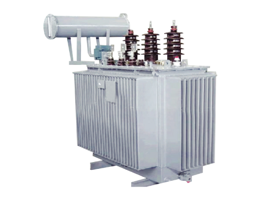
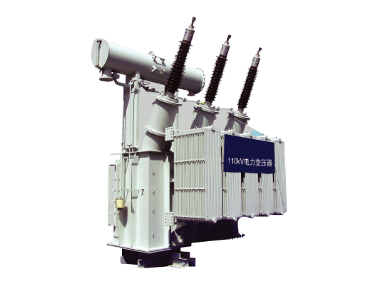
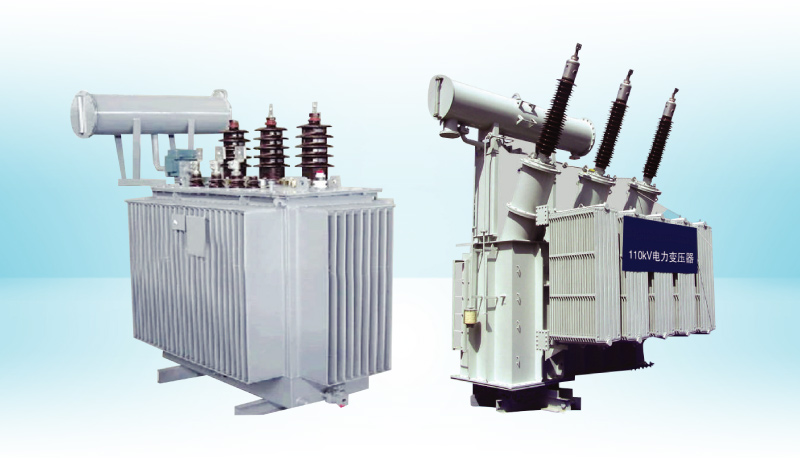
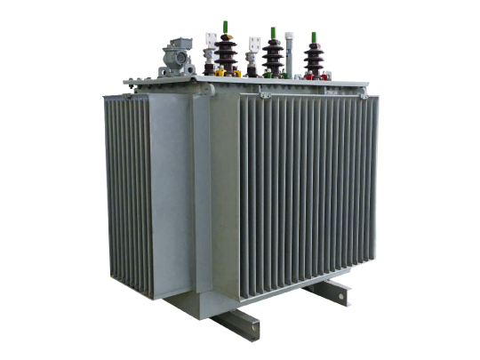
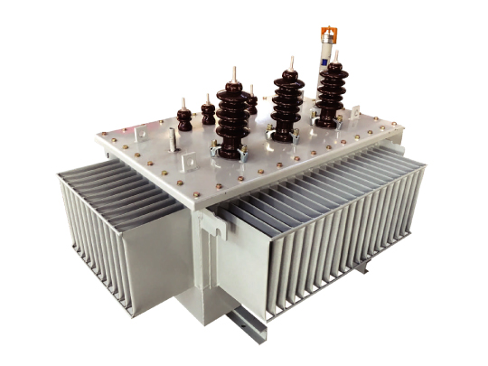
35kV~110kV Oil-Immersed Power Transformers
- 45° mitered hole-free laminations with burrs ≤0.02mm reduce no-load loss;
- Zero-clearance radial tightening ensures high short-circuit strength;
- Integrated constant-pressure drying and precise concentricity for uniform stress;
- Standardized lead routing minimizes partial discharge;
- Corrugated bell-type tank, shot-blasted with acrylic gaskets, prevents leaks;
- ONAN/ONAF cooling with airtight bladder, isolating oil from air;
- Low partial discharge, low loss, low noise, high reliability.
35kV~110kV Oil-Immersed Power Transformers Overview
Our 35kV~110kV oil-immersed power transformers are developed with advanced transformer technologies and engineered for urban and rural power networks. The series exceeds GB/T 6451 Technical Parameters and Requirements for Oil-Immersed Power Transformers and complies with JB/T 3837 Transformer Product Model Compilation Method, GB 1094 Power Transformers and applicable IEC standards. With low losses, low noise, reliable sealing and maintenance-friendly design, these transformers provide safe, reliable and cost-efficient performance for power transmission and distribution applications.
Product Features
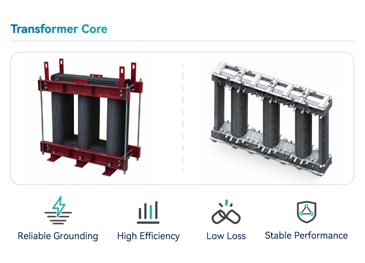
1. Transformer Core
The core features a multi-step lap joint structure with 45° mitred, hole-free laminations. Silicon steel sheets are processed on advanced longitudinal and transverse cutting lines, with burrs controlled within 0.02mm. Precision core stacking and strict assembly processes ensure optimal grain orientation, effectively reducing no-load loss. High-strength PET binding straps and platetype clamps enhance mechanical integrity and reduce stray losses. A dedicated yoke clamping process ensures uniform core compression.
The core, tie plates, beams and supports form a rigid integrated structure, delivering optimized stress distribution, lower no-load loss and reduced noise.
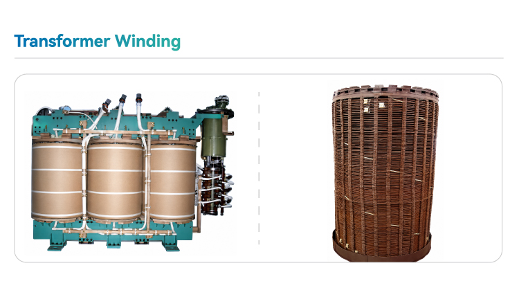
2. Transformer Windings
High-, medium-, low-voltage, and tap-changing windings are wound on insulated paper tubes. Low-voltage windings feature a helical design with axial oil ducts, while high- and medium-voltage windings use high-strength Dennison
paper-wrapped conductors, optimizing core fill and minimizing eddy and circulating current losses. Locking bars reinforce windings internally and externally, and zero-clearance radial tightening enhances mechanical strength and short-circuit resilience. Integrated oil channels reduce hotspot temperatures, prolonging transformer life. For on-load tap-changing transformers, an independent tap-changing winding ensures balanced ampere-turns, maintains stability, prevents deformation, and reduces axial forces during external short circuits, ensuring superior dynamic stability.
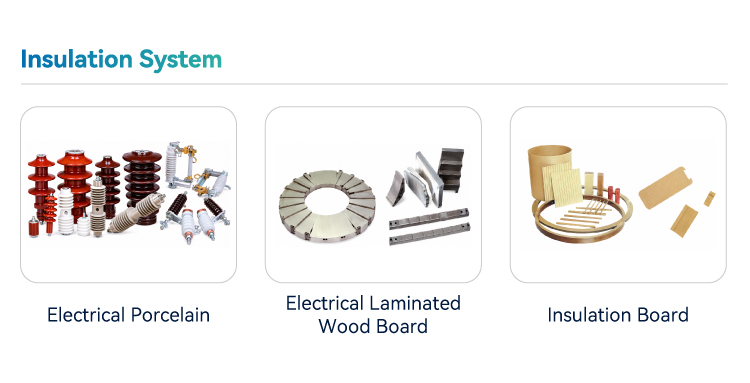
3. Active Part Insulation
The transformer’s active part insulation and winding assembly are completed in a fully sealed, clean workshop, meeting the cleanliness and temperature-control requirements for high- and ultra-high-voltage transformers. Kerosene vapor-phase drying is employed to further ensure dryness and cleanliness. Lower support plates and upper pressboards are made of high-quality electrical laminated wood with excellent mechanical and electrical properties. All spacers, blocks and related components are carefully treated and rounded to minimize partial discharge. Steel clamps and press pins are designed for high strength, with maximum contact surfaces and optimized arrangement of supports to ensure balanced winding stress and overall active part stability. The active part uses an integrated constant-pressure drying process, reducing assembly time after winding stabilization. Winding concentricity is carefully adjusted to maintain uniform magnetic core alignment, ensuring equal coil reactance and balanced mechanical stress, thereby enhancing short-circuit withstand capability. Lower clamps are rigidly positioned against the lower tank section using adjustable back-pressure pins, while the upper beam is fixed to the upper tank cover with epoxy resin. This ensures the active part remains securely in place during transportation and under axial forces in operation.
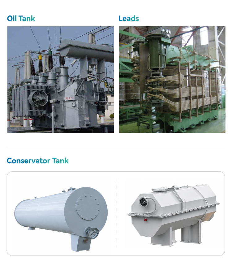
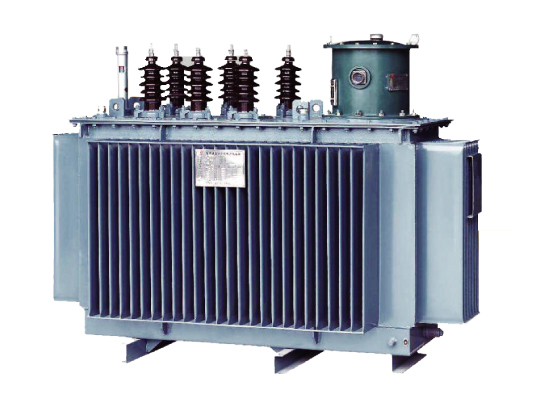
4. Leads and Connections
HV and MV tapping leads are securely supported and connected to the tap changer, while LV busbar leads are firmly fixed to the core clamping structure, ensuring high mechanical stability. Standardized lead routing and termination processes minimize partial discharge and enhance long-term operational reliability.
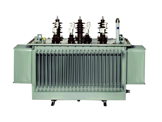
5. Transformer Tank
Medium- and large-sized transformers feature a bell-type tank design. The corrugated tank walls are formed in a single process using large folding equipment, eliminating additional reinforcement plates. This enhances mechanical strength, reduces weld-related leakage risks, increases effective heat dissipation area, and helps lower transformer noise through wall dispersion effects. Tank sealing areas receive specialized machining, and the entire tank undergoes shot blasting to remove oxide scale, burrs and welding slag, improving paint adhesion and ensuring a durable, high-quality finish. Radiators and other components are tested under simulated harsh operating conditions to verify leakage prevention. All flange surfaces are precision-machined and equipped with grooved positioning structures, and high-quality oil- and ozone-resistant acrylic rubber gaskets are used to prevent leaks. The upper and lower tank
sections are normally bolted together, with welded sealing available upon request.
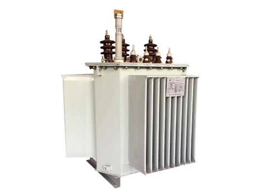
6. Cooling System and Accessories
Transformers are designed for ONAN/ONAF cooling. Under forced-air operation, they can run at full rated capacity; under natural oil-air cooling, loading is typically up to 67% of rated capacity. Radiators are arranged compactly and
efficiently, with fans mounted for horizontal or vertical airflow. The conservator features an oil-resistant, airtight bladder, fully isolating transformer oil from air to maintain a sealed insulation system. Stainless-steel corrugated conservators (internal- or external-oil type) are also available, offering maintenance-free operation and high reliability.
Leveraging advanced technology and a comprehensive quality assurance system, our transformers are engineered and manufactured for low partial discharge, low losses, low noise, and high reliability.
Service Conditions
- Installation type: outdoor
- Ambient temperature: Max. +40°C / Min. –30°C
- Altitude: ≤ 1,000m (temperature-rise correction required above 1,000m)
- Relative humidity: ≤ 90% (at 25°C)
- Installation environment: free from corrosive gases and excessive contamination
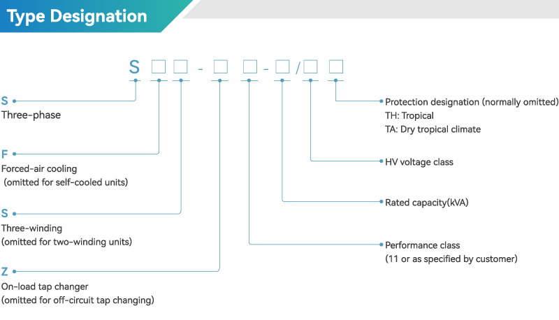
Type Designation
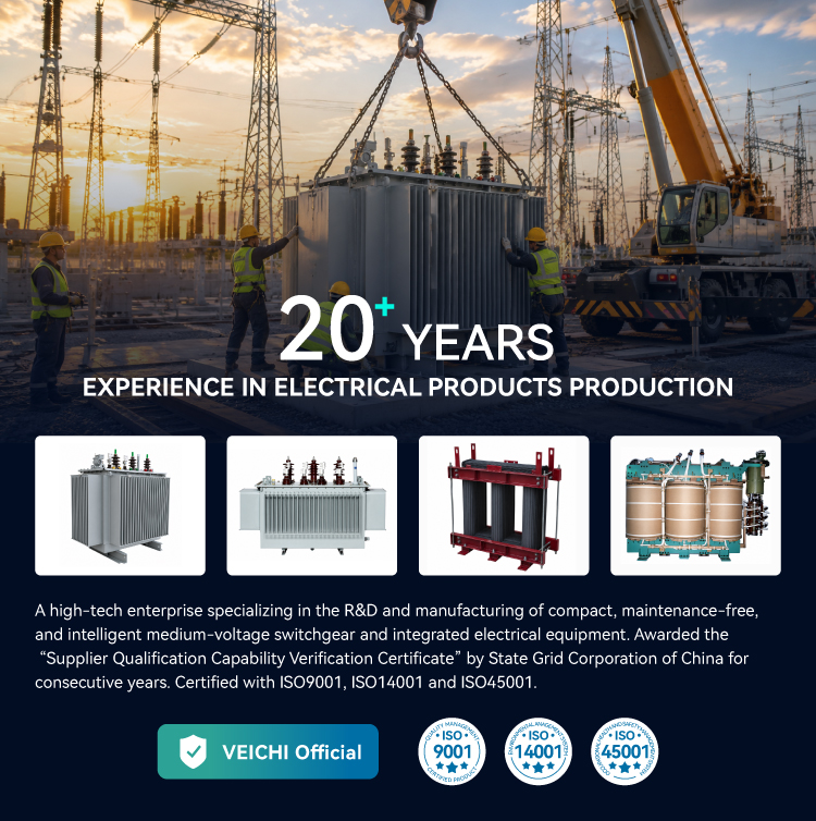
Company Advantages
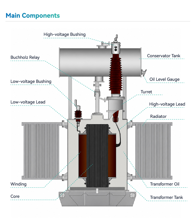
Main Components
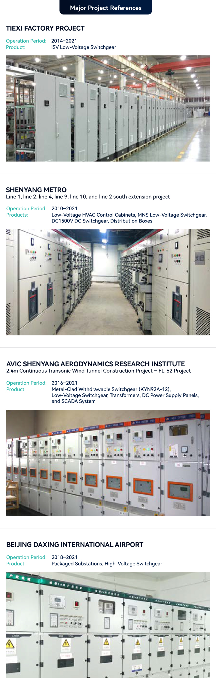
Project Case
Specifications
| Voltage class | 35kV~110kV |
|---|---|
| Tap-changing method | On-Load Tap Changer (OLTC) or Off-Circuit Tap Changer (OCTC) |
| Rated capacity | 315kVA~63,000kVA |
| Frequency |
50Hz |
|
Number of phases |
Three-Phase |
|
Vector group |
According to Chinese standards and customer specifications |
|
Short-circuit impedance |
According to Chinese standards and customer specifications |
|
Service conditions |
According to Chinese standards and customer specifications |
|
Cooling method |
ONAN / ONAF |
|
Insulation level |
According to Chinese standards |
Downloads
| File Name | Type | Language | File Type | Update | Download |
|---|


 Leave a Message